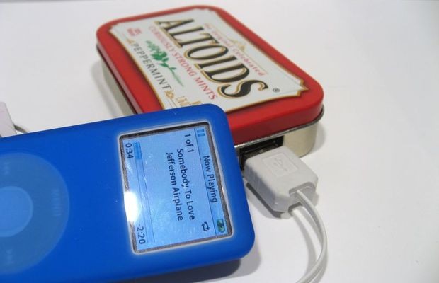
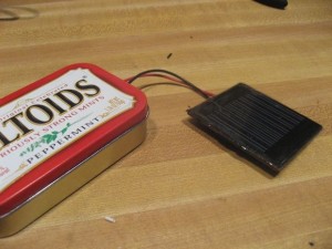
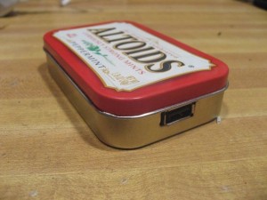
Make your own solar cell phone charger from an old solar light and an upcycled Altoids can. Is this the most awesome thing ever? Possibly, aside from those pugs in costumes and Neil Patrick Harris’ Choose your Own Adventure autobiography. This wonderful post comes to us through Instructables and from Joshua Zimmerman. If you don’t want to make your own, you can buy an upcycled Altoids charger or a DIY kit from his website BrownDogGadgets.com.
However, more options are available such as portable solar generators that also offer you the feature of recharging essential gadgets and keeping the outside lights on. Want to know more? You can browse on https://solargenerator.guide/best-portable-solar-generators/ You will also get the wall-socket charged battery packs that hold your power on for a while. Still, making your own solar cell phone charger sounds fascinating. Read on below are the steps to make your own super awesome solar cell phone charger.
Step 1: Gather the items you need
Parts:
- USB Charging Circuit
- Solar Panel 4V or greater
- AA Battery Holder
- AA Rechargeable Batteries
- 1N914 Diode
- Altoid Tin (or whatever)
- Wire
Tools:
- Soldering Iron
- Solder
- Tin Snips
- Melt Glue Gun and Glue
- Tape
Step 2: DC to USB Converter
The central brain of our project is a DC to USB converter circuit. This takes our AA power and changes it into the 5Vs we need for charging USB. There are several ways of doing this.
1) You can make one yourself using Lady Ada’s Minty Boost kit. It’s $20 and requires soldering. It also charges almost every gadget under the sun, including new Apple Products.
2) You can buy a pre-made circuit off eBay, or even off my website BrownDogGadgets.com. They cost around $10 and work with most everything; Kindles, iPhones, iPods, GPS, Android Phones. They’re great.
3) You can rip one out of a cheap USB charger. eBay and or Amazon are great places to look. Some of them don’t work with Apple stuff, so be careful or buy several.
Step 3: Choose Some Batteries
You need to use rechargeable batteries for this project. NiMh (nickel–metal hydride) AA batteries are easy to find, cheap, and reliable. You probably even have a few at home. Using two AAs in this project will mean the charger will have 2000 – 3000 mA of current. You could even have two sets of AA’s in parallel and boost that capacity to 4000 – 6000 mA.
An added bonus of rechargeable AAs is that you can take them out of the Solar Charger, charge them up or replace them, and be on your way.
Step 4: Choose Your Solar
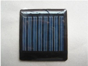
If we use two rechargeable AAs that put out a total of 2.4Vs we’re going to need a solar panel that is at least 3 – 4Vs just to meet basic levels of charging. The higher the voltage of our solar cell (or cells) the faster the batteries will be charged.
Now we’re also trying to fit this into an Altoids Tin, so we’re limited in space. There are some great 4V solar cells that perfectly fit into Altoids Tins so be sure to shop/look around.
Sure, a bigger and better solar cell would give added power, but it wouldn’t fit into the tin.
You could also use a combination of several smaller cells to get your four volts. For example, 2V cells are very cheap and small on ebay. You could easily connect two of those in a series to get your 4Vs.
Just remember that when charging NiMh batteries we don’t want to throw more than 10% of their capacity at them at any one time. For instance if your battery has a capacity of 2000 mA we can only use a solar cell that puts out 200 mA or less of current. This isn’t usually a problem unless you’re using a massive solar cell or a big combination of cells. None the less, keep this in mind.
Step 5: Wire Up The Solar
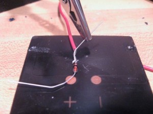
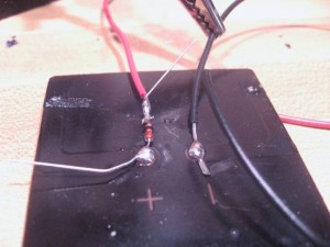
First, we’re going to wire up our solar panel. Connect the 1N914 diode directly to the solar panel. When soldering, make sure the black bar on the 1N914 diode is pointing away from the solar cell. The black bar is the negative side and prevents power backflow. Diodes only allow electrical current to flow in one direction – super important for DC circuits. If we put it in wrong we’re going to prevent power from flowing into our circuit.
Then attach a long wires to both the diode and negative tab on your solar cell. Then tape it up for protection.
Step 6: Connect The Battery Pack
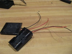
Now we connect the solar panel wires to the battery pack wires.
Just connect the positive wire (red) on the solar panel with the negative wire (black) on the battery pack, and then the negative wire (black) on the solar panel to the positive wire (red) on the battery pack.
Solder the wires where you twist them together, allow to cool for a second, then cover all exposed wiring with some electrical tape.
Easy as pie. Sweet sweet solar pie.
Step 7: Prepare the Charger
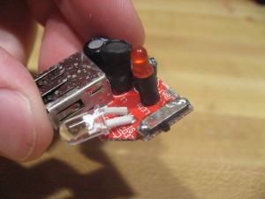
So the charging circuit I use also has a couple of LEDs on it. These in no way effect the USB charging and in fact are annoying. I remove them because they’re useless and a waste of power. This is why I’m cutting them off in the pictures below. You should NOT start cutting things away unless you know what you’re doing.
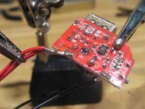
If you’ve bought a cheap charger to use, you have to take it out of its plastic housing, and disconnect any random wires or battery packs. What you should be mindful of, is where the power connects to your board. Mine has a nice little + and – sign to guide me. You need figure this out on your own depending on your situation.
Lastly, and most importantly, you should watch out for any switches. For instance mine has a little switch on the side to go from “Light” to “Off” to “USB.” I just keep mine set to “USB” as we don’t lose any power unless something is plugged in.
Step 8: Solder The Charger
Now all you have to do is solder that bundle of positive wires to the positive point on the board. Then all the negative, in this project black, wires to the negative point on the board.
You’re done with the circuit. You can test it now.
Usually I can charge a gadget just from sun. If it’s not sunny the circuit should charge via batteries.
Step 9: Cut Your Tin
I use Altoids Tins because they’re the prefect size for this project. Plus very cute. I also enjoy mints.
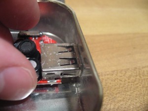
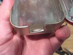
Just use some tin snips to cut a hole big enough for the USB port.
If you want to be fancy you can also use a Dremel and make a nice rectangle hole in the side of the tin. I’m lazy, so I just cut it away.
Step 10: Glue Everything In
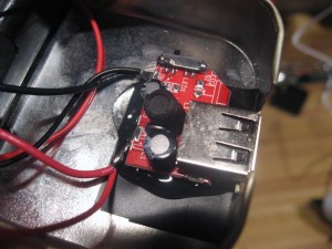
To be on the safe side I put down some electrical tape below my bare circuit board. Just to play it safe.
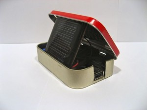
Now all you need to do is glue in your battery pack (though I use foam tape for that) and glue down your USB circuit.
Done and done.
Greenmoxie’s Field Guide to Green Living contains over 80 DIYs, recipes and tips on how to live greener and leaner. Learn to make fun upcycling crafts and furniture, make your own cleaning products, grow your own food and make ALL your own beauty products from face creams to mascara. Click HERE.


Very useful nowadays having solar mobile chargers.In info we need millions of this solar chargers with penetration of mobiles very high and very important communication device for all
Regards
yeNCee